
NO RESPONSIBILITY IS TAKEN FOR ANY DAMAGE CAUSED TO YOUR CONSOLE
please continue at your own risk
Most images can be clicked on for a larger view
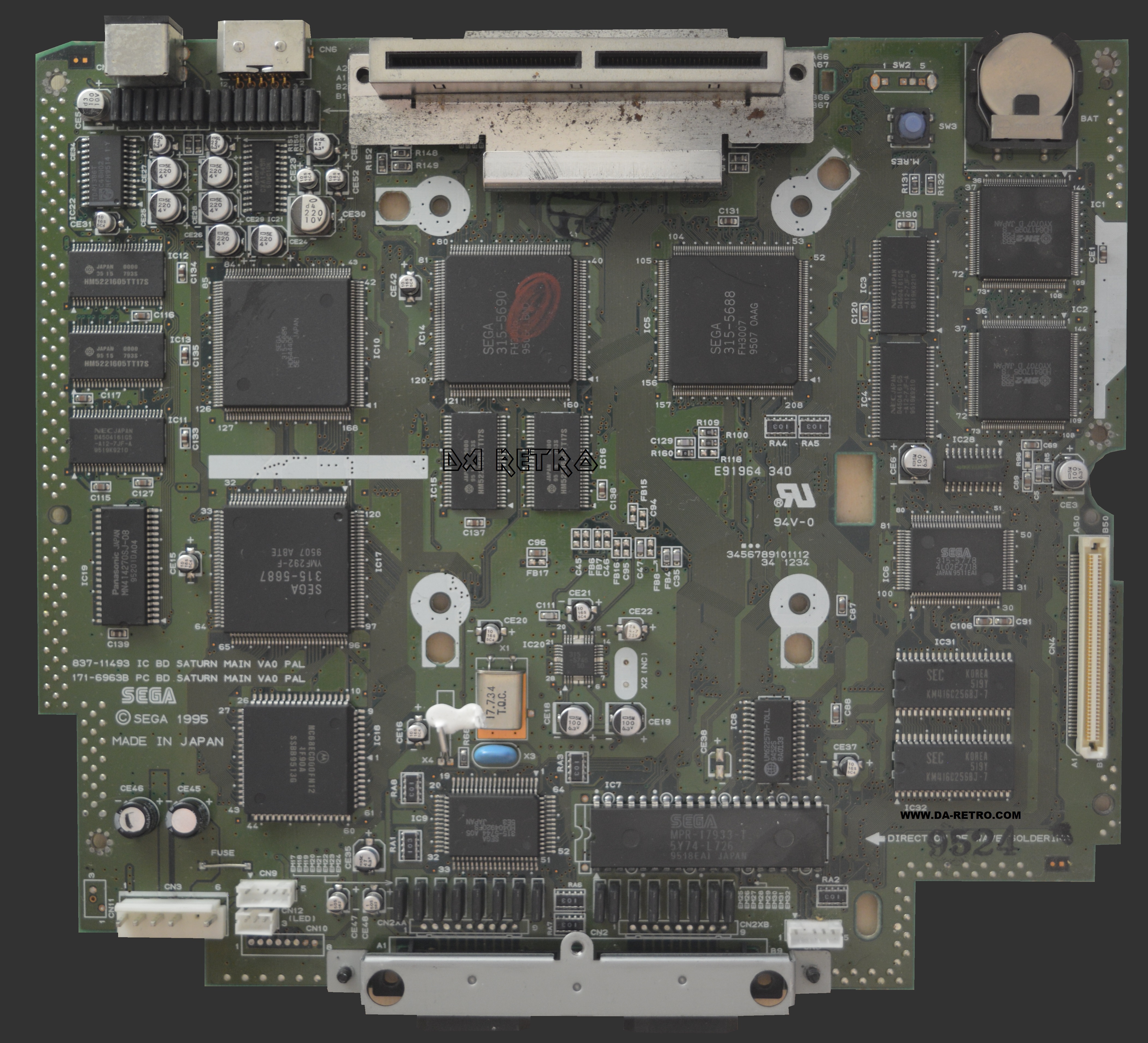
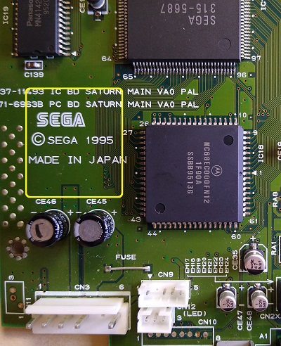
Sega Saturn VA0 Switchless Guide
Based on Serial Number 050
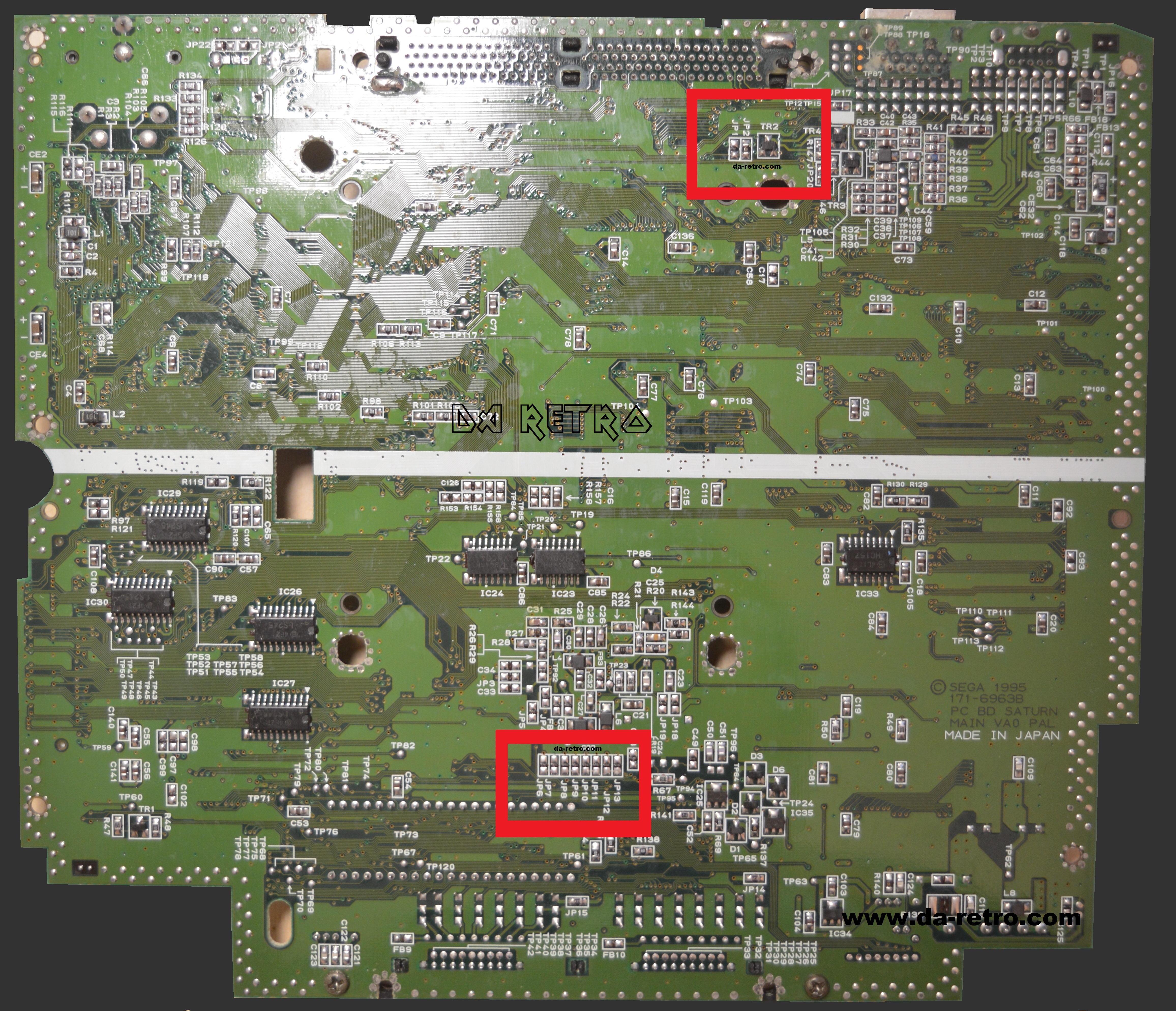
On the bottom of the board we need to break the links on four jumpers
numbers JP2, JP7, JP10 & JP12
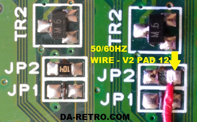
Desolder the resistor on JP2 and solder the a wire for the 50/60hz to JP2 ready to solder to the V2 pad 12
Cut the links between JP7, JP10 & JP12
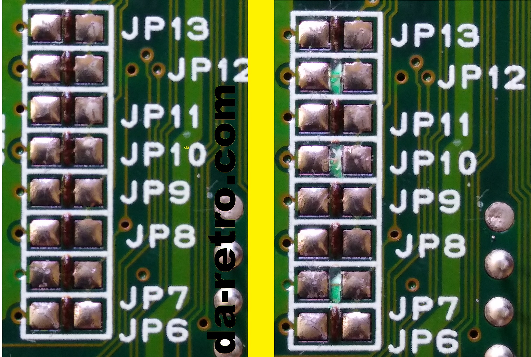
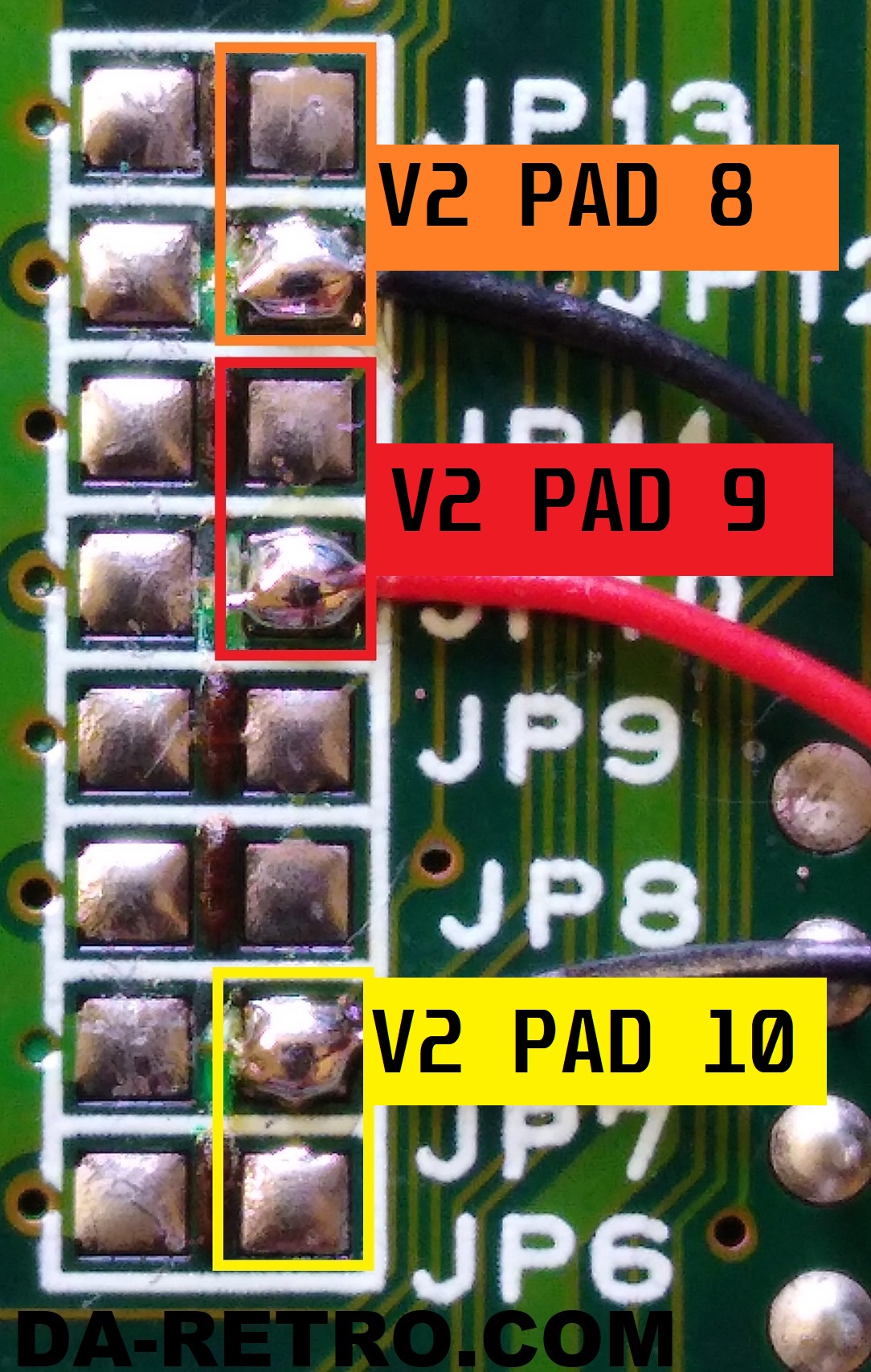
Connect a wire to each jumper to be connected back to the V2
You can connect to either of the two jumper pads marked for each.
JP6 or JP7 TO V2 PAD 10
JP10 or JP11 TO V2 PAD 9
JP12 or JP13 TO V2 PAD 8
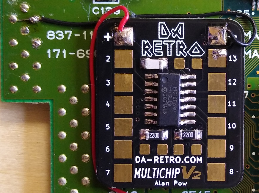
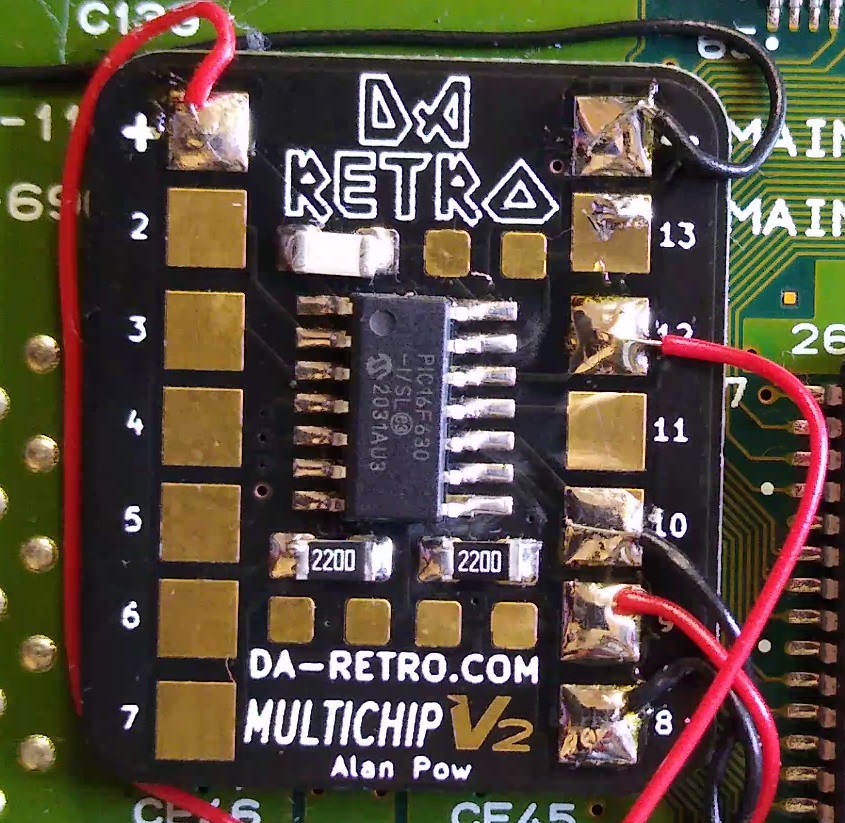
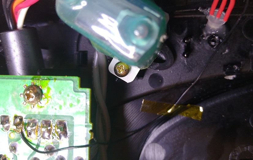
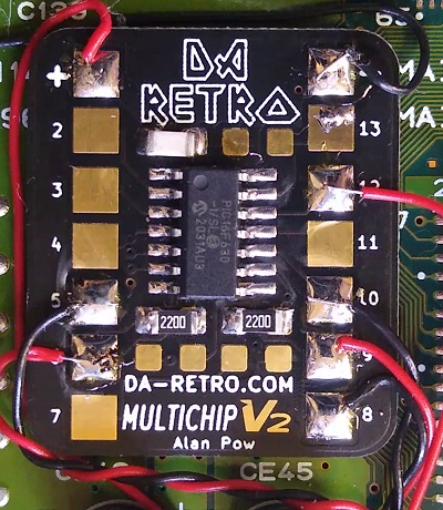
Find a suitable position for the V2 board, suggested location below
Wire up to a 5v source to the V2 chip, this can be taken from the fuse link wire
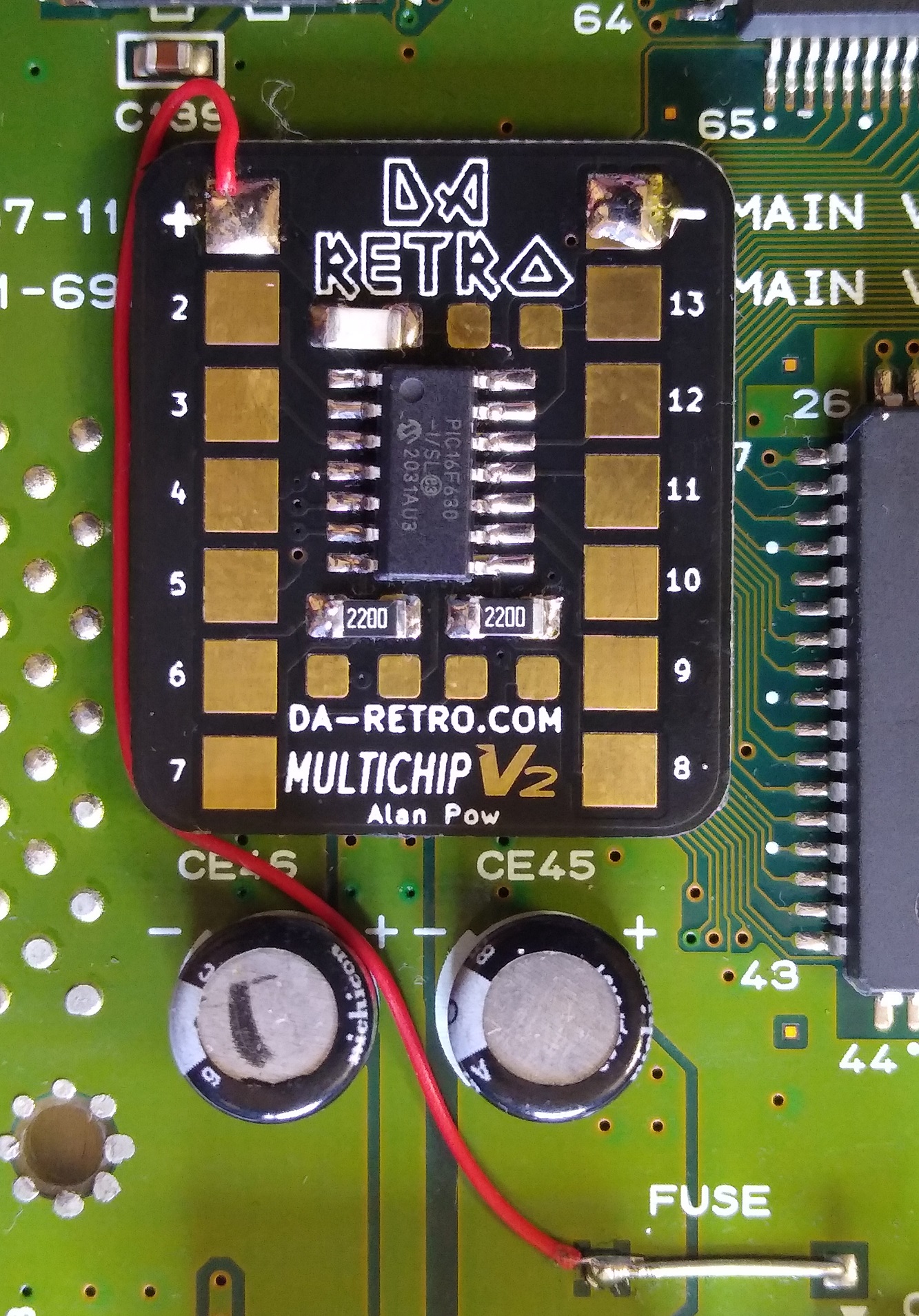
Wire a negative source to the V2 chip, this can be taken from the side of the board
Connect the region jumpers
JP6/7 to V2 PAD 10
JP10/11 to V2 PAD 9
JP12/13 to V2 PAD 8
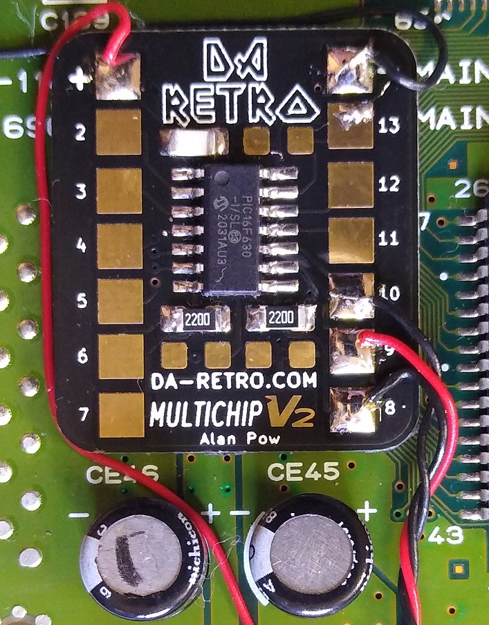
Connect JP2 jumper to V2 PAD 12
Solder wires to the LED
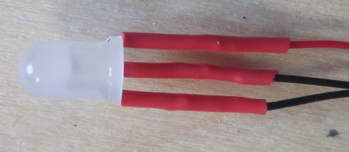
A small amount of hot glue in to the old LED space helps diffuse the light and holds the LED in place
You can wire the ground leg (middle led) straight to the ground of the power supply
Connect the other two LED wires to V2 pads 5 & 6
Cut the reset line on the reset button cable
Solder a wire to each of the cuts
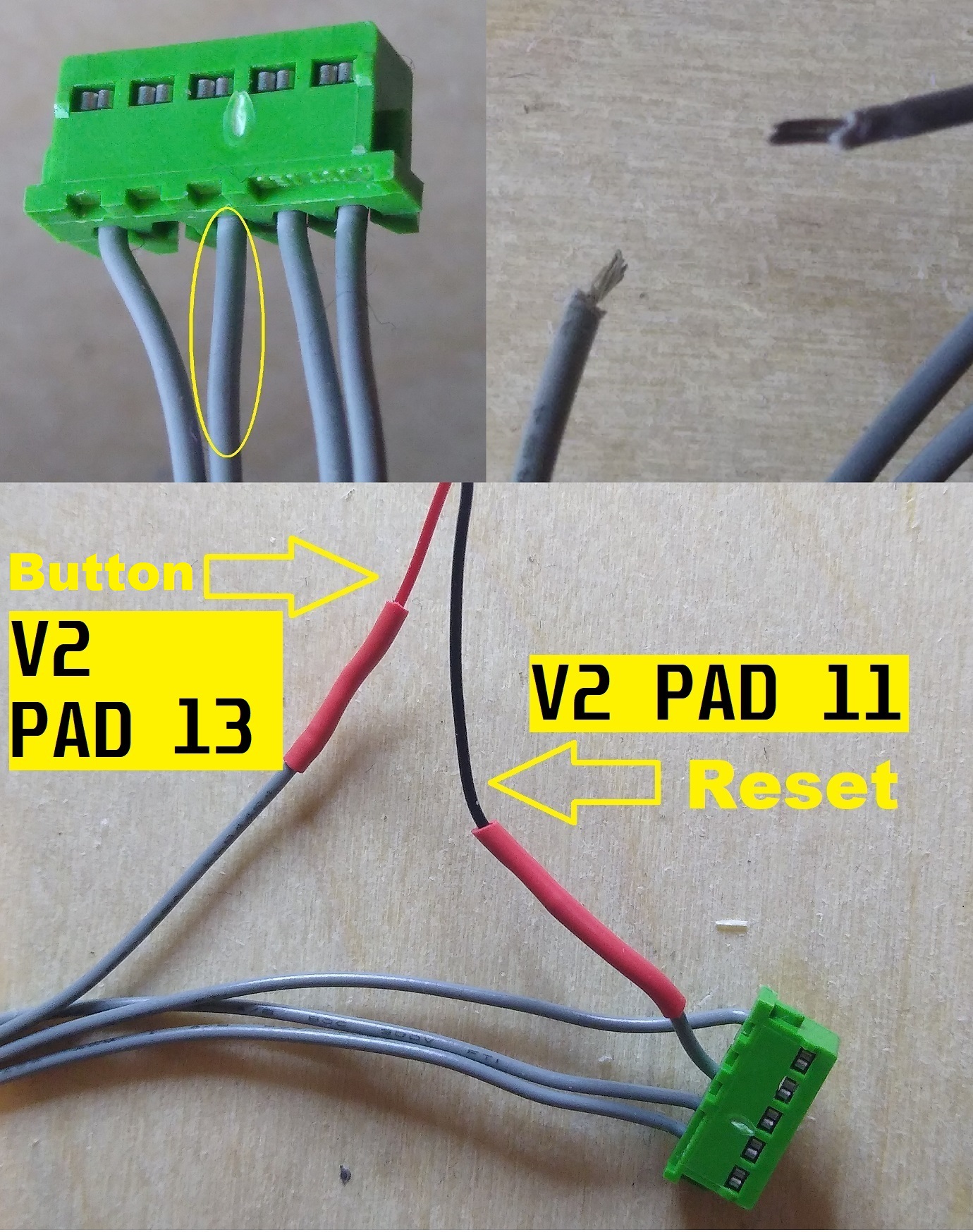
Connect the reset line wires to the V2
button wire to pad 13 & reset wire to pad 11

The mod is now complete. Please fully reassemble your console before attempting to turn on as the power supply contains high voltage
To check the regions are working correctly you can go into the Saturn's settings menu and read the region code in the bottom right of the screen.